Chamber furnace, metal insulation - HTK

The metallic HTK range of Carbolite Gero high temperature furnaces consists of metal heaters made of Molybdenum or Tungsten.
The HTK series, made of metal, is available in four distinct sizes. The smaller HTKs with capacities of 8 and 25 liters are usually used in laboratories for research and development. The larger 80 and 120-litre furnaces are mostly utilized as pilot manufacturing systems or for large-scale production. The front door design of these furnaces allows for easy loading and unloading.
The metallic furnaces are constructed using tungsten (HTK W) or molybdenum (HTK MO), resulting in the highest possible purity of the inert atmosphere and final vacuum level. Upon request, a high vacuum upgrade is available. The most commonly used gases include Nitrogen, Argon, Hydrogen, and its mixtures.
The HTK series features heating elements and insulation made of either tungsten (HTK W) or molybdenum (HTK MO). A retort can be utilized to guide the gas flow, particularly for debinding applications or to enhance temperature uniformity. The maximum temperature for the HTK W is 2200 °C, while for the HTK MO, it is 1600 °C.
Product Video: Chamber furnace, metal insulation - HTK
carbon free atmosphere, metal injection moulding (MIM), metallization, sintering, thermal debinding, pyrolysis, synthesis, annealing, tempering
| Furnace Type | Usable Volume | Max temp | Number of heated zones | Debinding Option | HTK 8 MO/W | 8 | 1600 °C / 2200 °C | 1 | Torch/ condensate trap | HTK 25 MO/W | 25 | 1600 °C / 2200 °C | 1 | Torch/ condensate trap |
| HTK 80 MO | 80 | 1600 °C | 4 | Torch/ condensate trap |
| HTK 120 MO | 120 | 1450 °C | 4 | Torch/ condensate trap |
Required infrastructure
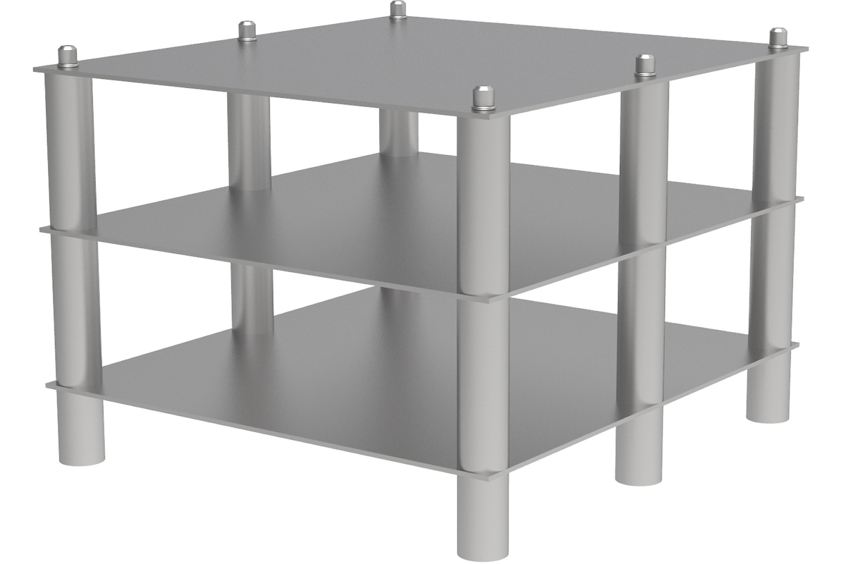
Usable space in the retort H x W x D [mm]
Number of plates*
Plate dimensions [cm²] *
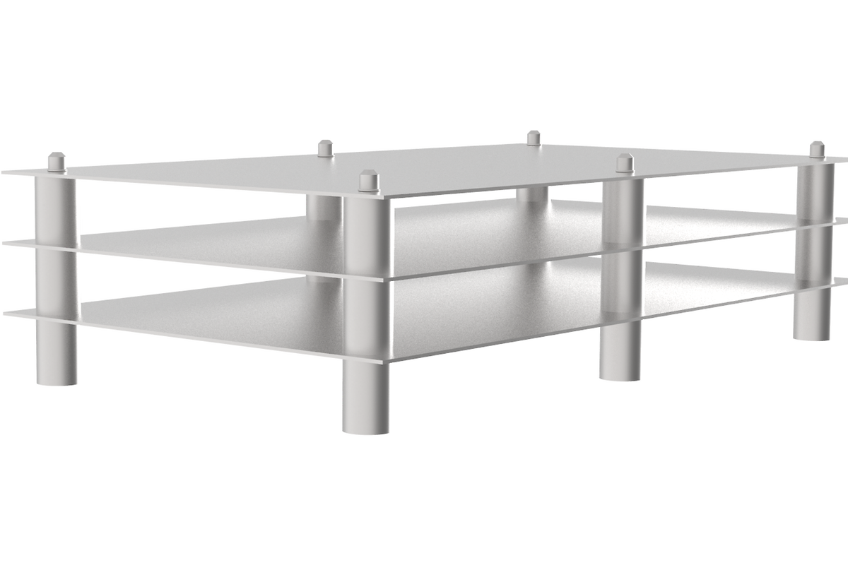
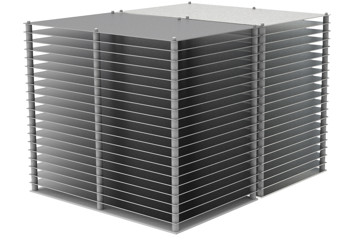
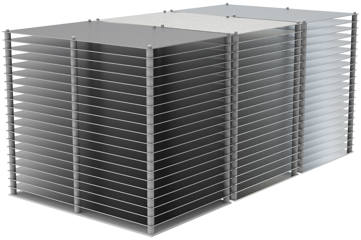
Picture of sample rack
160 x 180 x 180
3
225
240 x 240 x 400
3
860
380 x 410 x 500
40
930
380 x 400 x 770
60
930
* The displayed values refer to a typical retort layout. The specific arrangement can be customized to meet the requirements of the customer.
The HTK-MIM-3 furnace program enables debinding and sintering of MIM components in two stages. The program's progress is displayed in a diagram, and important parameters such as pressure, gas flow, and gas type are recorded. The debinding stage utilizes partial pressure and high nitrogen gas flow, while the sintering stage focuses on temperature uniformity, resulting in a consistent density of the MIM parts.
HTK 8 – 80 furnaces consist of:
Exemplary cross section of a HTK 8 molybdenum
HTK 120 furnaces consist of:
Heating cassette of the HTK 120, CAD drawing. Designed for highest lifetime and easy maintenance.
The torch of the afterburner ensures controlled conversion of remaining flammable or toxic volatiles into non-flammable gases.
The condensate trap may be installed for binder handling. During the process the trap is cooled to condense the binder. After the process the trap can be heated to release the binder safely which has been liquified.
The stand alone safety purge tank ensures full safety for hydrogen applications. The furnace can only be started, if the tank is completely filled. Therefore the furnace is flood with nitrogen gas in case of major errors, such as power failure etc. The size is adjusted according to the furnace volume.
Heated gas outlet and vacuum line of the HTK 120
Stand alone safety purge tank
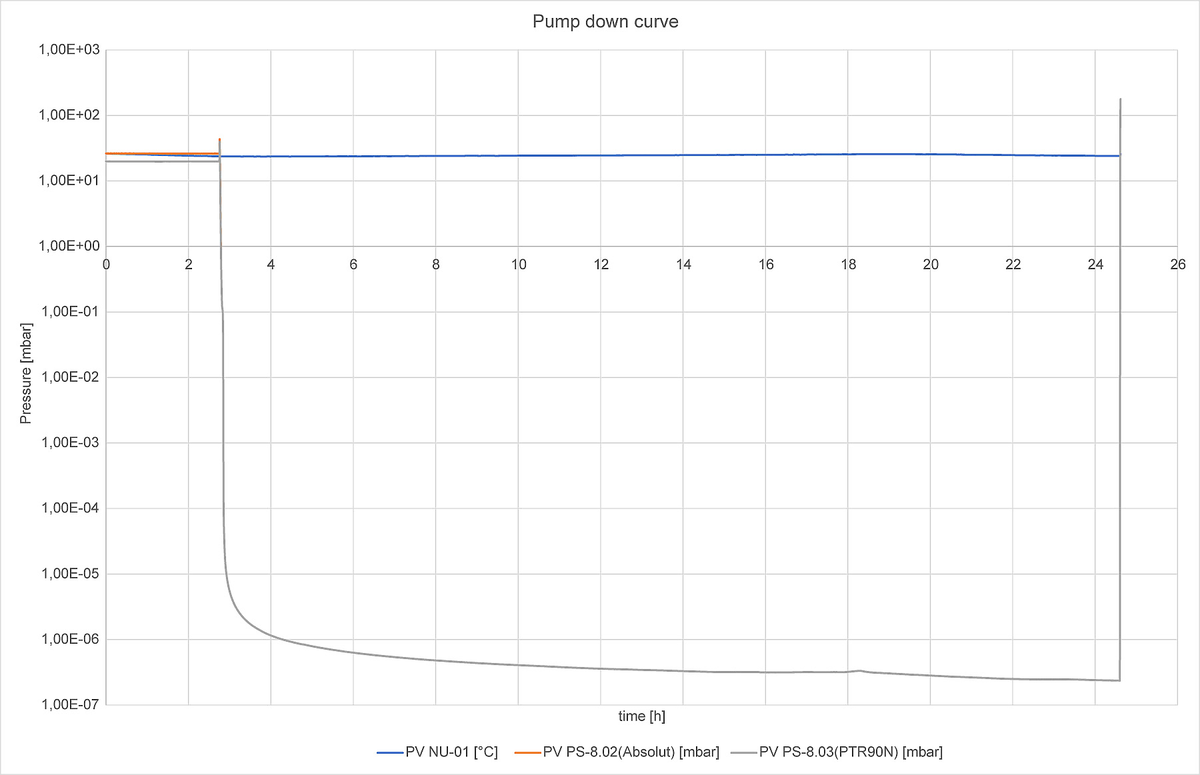
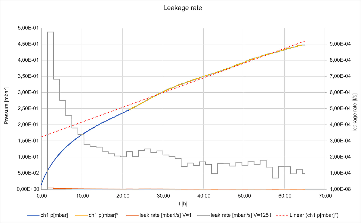
With the high vacuum upgrade the leakage rate results in values below 10-3 mbar*l/s. The leakage rate is determined by evacuating the furnace, closing all valves and meassuring the pressure increase over time. The desorption of water molecules from the metal surface takes approximately 20 h, and leads to a faster increase in pressure, represented by the blue line.
Measured under controlled laboratory conditions. Results may vary depending on process-specific variables, e.g. gas flow rates, vacuum levels, and sample material, size/density.
Measured under controlled laboratory conditions. Results may vary depending on process-specific variables, e.g. gas flow rates, vacuum levels, and sample material, size/density.
Cross section of HTK 8 with high vacuum upgrade. The turbo pump is at least connected via an DN100 flange.
High vacuum upgrade
Schematic of a turbomolecular pump for high vacuum applications.
The furnace is operated via a 12" or 19" touch panel controller. It provides an overview of the furnace and its behaviors and allows the user to preform any possible adjustments to the furnace.
| Size of Panel | 12" |
| Number of programs | 12 |
| Export data | .csv |
| Remote access | Yes |
| Keyboard | No |
| Remote maintenance | No |
| Online changes | No |
| MFC | Yes |
| Rotameter | Yes |
| Heated gas outlet | Yes |
| Turbopump | Yes |
| Hydrogen | No |
| Partial pressure | No |
| Sliding TC | Yes |
| Size of Panel | 19" |
| Number of programs | 20 |
| Export data | .csv |
| Remote access | With Siemens software |
| Keyboard | Optional |
| Remote maintenance | Optional |
| Online changes | Yes |
| MFC | Yes |
| Rotameter | No |
| Heated gas outlet | Yes |
| Turbopump | Yes |
| Hydrogen | Yes |
| Partial pressure | Yes |
| Sliding TC | Yes |
Chamber furnaces are quite easy to load and unload, due to the front loading concept. Smaller furnace can be loadaed manually, bigger units can be loaded by a manual fork lift. The rectangular design of the water cooled vacuum vessels allows the unit be be designed highly compact. This is why the units do not require much space in the workshop and are perfectly suited for laboratories. All HTK type furances are mounted on a single frame and can be easily delivered to customers all over the world. However, for bigger furnace volumes, the vessel is designed cylindrical, as for the HTK 120.
This depends on the process. Some materials, such as stainless steel, 316L, titanium etc. cannot be heat treated in a graphite furnace, especially when the performance of the part is of importance. In such a case metallic furnaces are recommended due to their high purity atmospheres as well as hydrogen and high vacuum abilities.
In a graphite furnace, hydrogen would react with the graphite heating elements and insulation above 1000 °C. The higher the temperature, the faster the graphite parts wear which generates hydrocarbons and causes reactions with the sample. In a metallic furnace the resulting atmospthere is pure.
The lower the variaty of materials inside the furnace chamber, the less is the cross-contamination inside the furnace. This leads to a purer atmosphere within the furnace. Furthermore, the working vacuum is better, due to high boiling points and low vapour pressure of the bespoken metals. The Carbolite Gero vacuum furnace design consists of multiple layers of radiation shields to ensure very low energy consumption. Those layers act like a “mirror” reflecting the thermal radiation, hence insulating the furance. The remaining heat is taken away by cooling water surrounding the vacuum vessel.
Carbolite Gero enables adjustable pressure levels between 10 and 1000 mbar. With a variable pressure, the customer can adjust the gas density and therefore the Reynolds number as desired. This ensures a positve gas flow under reduced pressure, evaportating the binder at lower temperatures. This is advantageous for many applications. However, hydrogen partial pressure requires a lot expertise in order to handle it safely. We use dedicated software and hardware solutions to ensure full safety under these conditions.
Content may be subject to modifications or corrections