Metal Injection Moulding (MIM) Debinding furnace - EBO
 Debinding furnace - EBO")
 Debinding furnace - EBO")
- Max temp: 150 °C
- Volume: 120 to 250 litres
- For catalytic debinding
- Product details
Metal Injection Moulding (MIM) is a modern manufacturing technique that involves injecting a “feedstock” into moulds to create complex shaped metal components. Carbolite Gero offers furnaces and ovens specifically optimized for the heat treatment process steps required by this application.
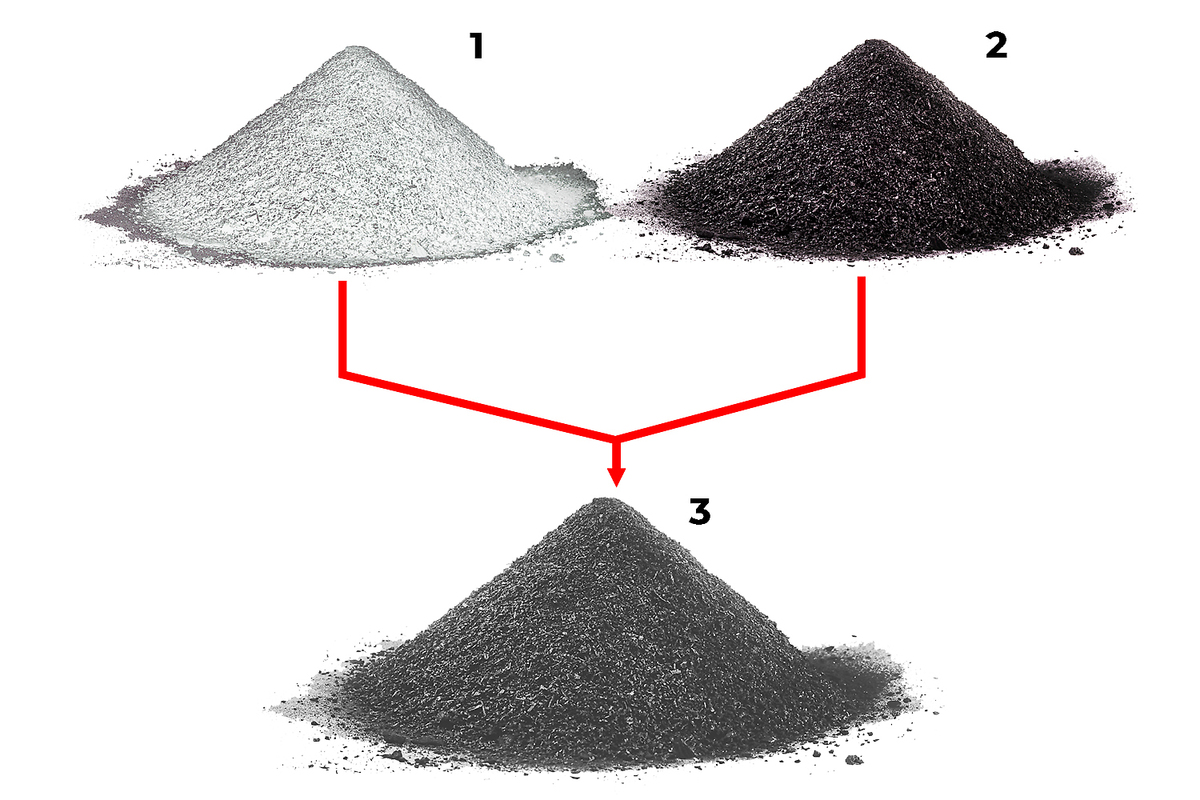
Metal Injection Moulding (MIM) is a manufacturing technique that involves injecting a “feedstock” into moulds to create complex shaped components with a high rate of reproducibility. The feedstock is a mixture of powdered metal and a polymeric binder that holds the material together. Before the components can be used, the binder must be removed, and the internal structure of the part strengthened; this is achieved by subjecting the components to the heat treatment processes of debinding and sintering in a furnace or oven.
Binder (1) and metal powder (2) are combined to make up the feedstock (3)
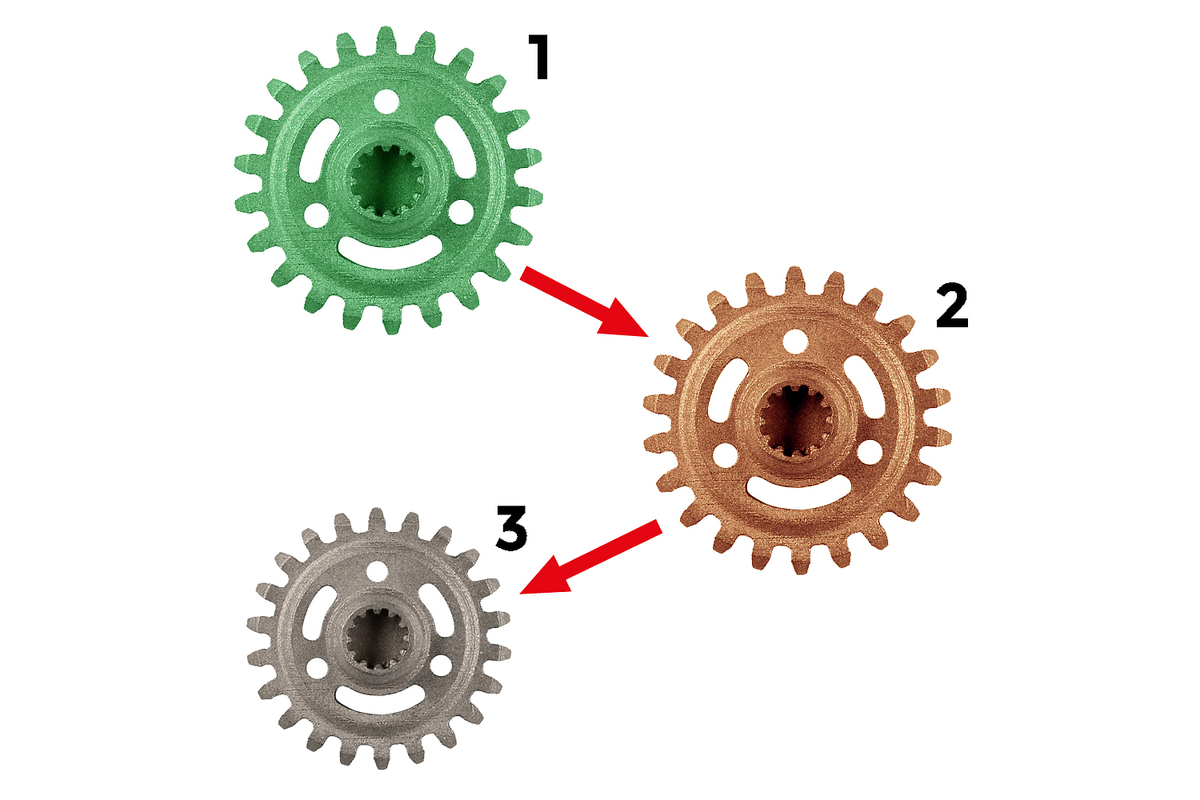
Green part (1) formed by metal injection moulding, brown part (2) after binder removal and finished part (3) after sintering
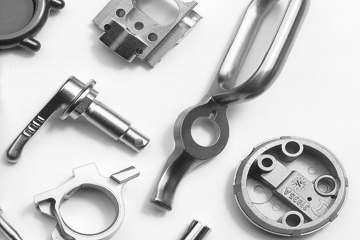
Example of some finished metal parts produced via metal injection moulding
This is the process of removing the binder from the green part. It can be achieved either catalytically, where the binder is removed using a combination of catalytic additives, solvents, and water, or thermally, which requires heat treatment under a modified atmosphere in a furnace or oven. The method required depends on the type of feedstock used. Components that have been through the this process are subsequently referred to as “brown” parts.
Depending on the type of feedstock used, it may be necessary to both chemically and thermally debind parts. The chemical process will remove the majority of the binder, whilst the thermal process removes the residual binder, also referred to as “backbone binder”. This process is often referred to as “rest debinding”.
Carbolite Gero can provide furnaces and ovens suitable for either catalytic or thermal applications.
This is the process of heat treating Metal Injection Moulding (MIM) components that have first been subject to the debinding process (brown parts). The aim of sintering is to change the internal microstructure of the components to improve their overall density and ultimately, strength. This is achieved by heating the metal parts in a furnace or oven under an inert atmosphere to approximately 20% below the melting point of the metal, allowing the atoms to diffuse through the microstructure and fuse together in a denser formation. During sintering, the metal parts will experience some shrinkage, with a 15-22% reduction in size, depending on the metal used, and the final density of the part.
The temperature profiles, the atmosphere, and the temperature uniformity within the furnace during both, debinding and sintering have to be controlled very accurately to avoid distortion and the formation of cracks and bubbles. The inert or reducing atmosphere is also important to prevent the oxidation of parts.
The main binder is shown in blue and can be removed catalytically.
The backbone binder is shown in green. It can only be removed thermally between 300°C and 600°C in a furnace or oven. This process is often carried out in partial pressure, which reduces the temperature due to the additional pressure exerted by the vapourised backbone binder.
Catalytic binder removal can be performed inside Carbolite Gero’s EBO furnace.
Nitric acid (HNO3) is evaporated and carried around the furnace by a flow of nitrogen, where it is passes over the green parts.
The nitric acid cracks the main binder, creating formaldehyde (CH2O), which is gaseous and explosive in concentrations between 7%-73%. The gas flow directs the formaldehyde towards the furnace gas outlet where it is then safely combusted using an active torch afterburner.
Example
Green parts after catalytic debinding (left): Diameter: 27.86 mm / Mass: 11.89 g
Green parts after full sintering (right): Diameter: 24 mm / Mass: 11.71 g
➔ Total reduction in mass after rest debinding: 1.5%
The feedstock is injected into the mould and formed into the desired shape. The binder is highlighted in blue and green.
At this point, the MIM part is referred to as the “green part”.
During the catalytic / chemical debinding, the main binder (blue) is removed, leaving only the backbone binder (green), which must be removed thermally in a furnace.
During the rest debinding process, the backbone binder (green) is removed, and the MIM part is now referred to as the “brown part”.
In order to increase the density and strength of the part, it must now be sintered. At this point, the particles are already starting to diffuse and adhere to each other.
During the sintering process, the atoms within the MIM part diffuse through the structure, and fuse together, increasing the overall density of the part.
During sintering in a furnace, the microstructure of the MIM part is noticeably denser, with fewer gaps between atoms. The sintering process results in some shrinkage, with some parts experiencing up to a 22% reduction in size. This is a normal part of the Metal Injection Moulding (MIM) process, and should be accounted for during the initial design of the moulds.
Carbolite Gero offer two main multi-step solutions for the heat treatment of Metal Injection Moulding (MIM) components.
The first option is a combination of the EBO 120 oven and HTK 120 furnace. Catalytic removal of the binder is carried out in the EBO, whilst both thermal debinding and sintering can be performed inside the HTK.
The main benefit of this solution is that the entire process can be carried out using only two furnaces. It is important to note that while initially more cost-effective, removing the binder can be a dirty application which could contaminate and damage the molybdenum or tungsten chamber of the HTK furnace over time.
However, by using an HTK furnace for both binder removal and sintering, it is possible to debind in a hydrogen atmosphere under partial pressure. This is not possible when using the GLO furnace.
Example:
Please note: The cycle times stated are typical values for a specific process. Cycle times will vary depending on individual applications and customer requirements.
The second option is a combination of the EBO 120, GLO 260, and HTK 120. Catalytic removal of the binder is carried out in the EBO, thermal binder removal in the GLO, and sintering in the HTK furnace.
Whilst this solution incorporates an additional furnace into the process, overall it can prove a more cost-effective solution, as the construction of the HTK sintering furnace is protected from contamination, thus maintenance costs are reduced.
Example:
Please note: The cycle times stated are typical values for a specific process. Cycle times will vary depending on individual applications and customer requirements.
In order to achieve the best possible conditions to remove the binder of MIM components, the gas flow needs to be continuous and turbulent to enable it to reach all samples placed within the furnace. The turbulence assists in the removal of binder from green parts during the application.
Carbolite Gero has worked closely with academic institutions to carry out CFD (Computational Fluid Dynamics) simulations to test and improve gas flow inside furnace chambers typically used for Metal Injection Moulding (MIM) applications.
Temperature uniformity is the maximum temperature deviation within the usable volume of the furnace chamber. For example, if the furnace is set to 600°C and it has a stated temperature uniformity of ±5°C, then temperature within the usable volume cannot deviate below 595°C or above 605°C.
Temperature uniformity is crucial during the sintering of Metal Injection Moulding (MIM) components in a furnace, as the aim is to ensure that all parts have an equal amount of shrinkage and density.
Carbolite Gero furnaces are available with multiple heated zones to ensure the temperature inside the chamber is consistent throughout.
Formula for calculation of temperature uniformity:
Carbolite Gero’s HTK furnace range has been designed specifically to optimise large-scale metal injection moulding heat treatment processes. For example, the HTK120 retort enables the operator to load up to three stacks of samples, each comprising 20 trays (380 x 240 x 0.5 mm in size). The distance between trays can be adjusted to accommodate the geometry of a wide range of samples.
The design and configuration of the racking enables gas to flow through each layer and around each MIM part placed inside. To achieve this, four special gas inlet diffusors direct the flow horizontally through the layers of racking. Each inlet is connected to a separate gas flow, the rate of which can be individually set to maximise performance depending on the individual requirements.
A special gas outlet plate is fitted to ensure that the gas is distributed uniformly throughout the volume of the retort chamber of the furnace rather than solely through the centre.
A range of touchscreen controllers and programmers are available, allowing operators to easily input for heat treatment programs. Additionally, predefined programs for (rest-) debinding and sintering of some of the most commonly used materials (316-L, CrMo4, 8620 etc) are available as a standard setting within the controller software. Settings for other materials can be enabled, following consultation with Carbolite Gero.
Carbolite Gero products and services are available via a global network of daughter companies and fully trained distributors. Our staff will be happy to assist with any inquiry you might have.
Contact us for a free consultation and talk to a product specialist to find the most suitable solution for your application needs!
In addition to Carbolite Gero furnaces for heat treatment, Verder Scientific's other product lines offer further solutions for the entire metal injection moulding process as well as additive manufacturing technologies in general:
There are two steps in Metal Injection Moulding (MIM) that require a furnace: Debinding to remove the binder of the green part and sintering to improve the overall density and strength of the metal part.
Depending on the individual application, either two or three furnace systems are typically required. One for catalytic removal of the binder and then either one or two furnaces for thermal debinding and sintering.
Carbolite Gero furnaces designed for Metal Injection Moulding processes feature benefits such as low energy consumption, data logging, touchscreen controller interface, and easy handling of waste binder without the need for condensate traps. Our furnaces for catalytic binder removal are water heated, preventing any condensation of nitric acid within the unit; our high-stability heating cassettes ensure that debinding and sintering processes can run 24/7.
Yes, partial pressure with Ar, N2 or H2 is possible in a furnace. The pressure can be adjusted in the controller software to between 100 – 1000 mbar. The opening angle of a pneumatic valve is set to ensure the pressure within the furnace vessel is kept at a constant level. For the hydrogen partial pressure mode, all required safety standards are applied and certified by TÜV.
The excellent temperature uniformity within Carbolite Gero’s furnaces designed for Metal Injection Moulding is achieved by using a symmetrical heating element arrangement, multiple heating zones, and a sealed retort to contain the modified atmosphere. The retort also protects the furnace from any binder that may condense during the process.
Depending on the size of the Metal Injection Moulding furnace, when processing using partial pressure, the binder is either handled by condensate traps for smaller furnaces or by dissolving the binder in oil. The latter is extremely advantageous for larger units, since the maintenance effort is drastically reduced compared to condensate traps.
Carbolite Gero offers a range of different sized furnaces for catalytic and thermal debinding as well as sintering in Metal Injection Moulding processes. Custom manual handling systems can be provided to transfer parts between the different furnaces, on request.
Titanium can be sintered in either a pure Argon atmosphere, or under high vacuum. Carbolite Gero’s extensive experience in vacuum technology enables us to deliver furnace systems with the lowest leakage rates, thus the highest vacuum capabilities. Dependent on requirements, we can equip systems with suitable vacuum pump accesories.
 Background information")
 Debinding furnace - GLO")
 Sintering Furnace - HTK")


 debinding")


